
Mesh Shaders as Replacement for Hardware Tessellation?
Introduction
Mesh shaders represent a notable evolution in modern graphics pipelines. They are often positioned as a potential “silver bullet” capable of replacing the traditional geometry processing stages—namely vertex, tessellation, and geometry shaders. For instance, the DirectX specification frames their role as follows:
There will additionally be a new Amplification shader stage, which enables current tessellation scenarios. Eventually the entire vertex pipeline will be two stages: an Amplification shader followed by a Mesh shader. […] The Amplification shader allows users to decide how many Mesh shader groups to run and passes data to those groups. The intent for the Amplification shader is to eventually replace hardware tessellators.
It was the latter claim that made me suspicious and motivated me to dive a bit into this topic.
Glossary
For this blog post, I have used both Vulkan and DirectX resources. Therefore, terminology is clarified upfront to avoid ambiguity:
| Term | Explanation |
|---|---|
| “Graphics Pipeline” | A rasterization-based graphics pipeline with classical shader stages, and classical geometry shader stages: vertex, tessellation, and geometry shaders |
| “Graphics Mesh Pipeline” | A rasterization-based graphics pipeline with amplification/task and mesh shaders |
| “Vertex Shading” | Rasterization using a classical graphics pipeline |
| “Mesh Shading” | Rasterization using a graphics mesh pipeline |
| “Task Shader” | First shader stage in graphics mesh pipelines (Vulkan terminology) |
| “Amplification Shader” | First shader stage in graphics mesh pipelines (DirectX terminology) |
| “Mesh Shader” | Second shader stage in graphics mesh pipelines |
| “Workgroup” | GPU threads that are scheduled to process the same instructions in a single instruction multiple data (SIMD) fashion |
| “Invocation” | A GPU thread (Vulkan terminology) |
| “Lane” | A GPU thread (DirectX terminology) |
Table 1: Relevant terms, some of which are used in Vulkan, others in DirectX, some in both APIs.
Graphics Pipelines
As a quick reminder, Figure 1 shows the structure of classical graphics pipelines, to be compared to a mesh shading-based graphics pipeline in Figure 2, where all the geometry stages have been replaced by two compute shader-style stages: task and mesh shader.

Figure 1: Stages of a classical rasterization-based graphics pipeline, with several fixed-function stages (input assembly, tessellator, and rasterizer) and several programmable stages (vertex shader, tessellation control shader, tessellation evaluation shader, geometry shader, and fragment shader).

Figure 2: Stages of a graphics mesh pipeline, where only the rasterizer remains as a fixed-function stage. Two new programmable shader stages (task and mesh shader) replace all geometry stages of classical rasterization-based graphics pipelines.
Task and mesh shaders are, generally speaking, more generic and versatile stages compared to their counterparts in classical graphics pipelines. One could say that they offer more freedom, but also place more of the optimization burden on graphics programmers. From a GPU’s perspective, fewer fixed-function steps are active since input assembly and the hardware tessellator are not usable/not supported in graphics mesh pipelines.
Faster Than Vertex Shading
Early experiments replacing vertex shaders with mesh shaders reported highly promising results. For example, Arseny Kapoulkine demonstrated in niagara: Tuning mesh shaders a throughput of 20.7B rasterized triangles per second with mesh shading, compared to 7.4B/s using vertex shading.
In our own work on Conservative Meshlet Bounds for Robust Culling of Skinned Meshes, we observed a less dramatic but still clear performance improvement: With meshlet culling disabled in task shaders—ensuring identical geometry workloads and a fair comparison—vertex shading renders the scene shown in Figure 3 at 27.1 FPS, whereas mesh shading achieves 32.8 FPS, corresponding to a 21% speedup on an RTX 3050 Laptop GPU.
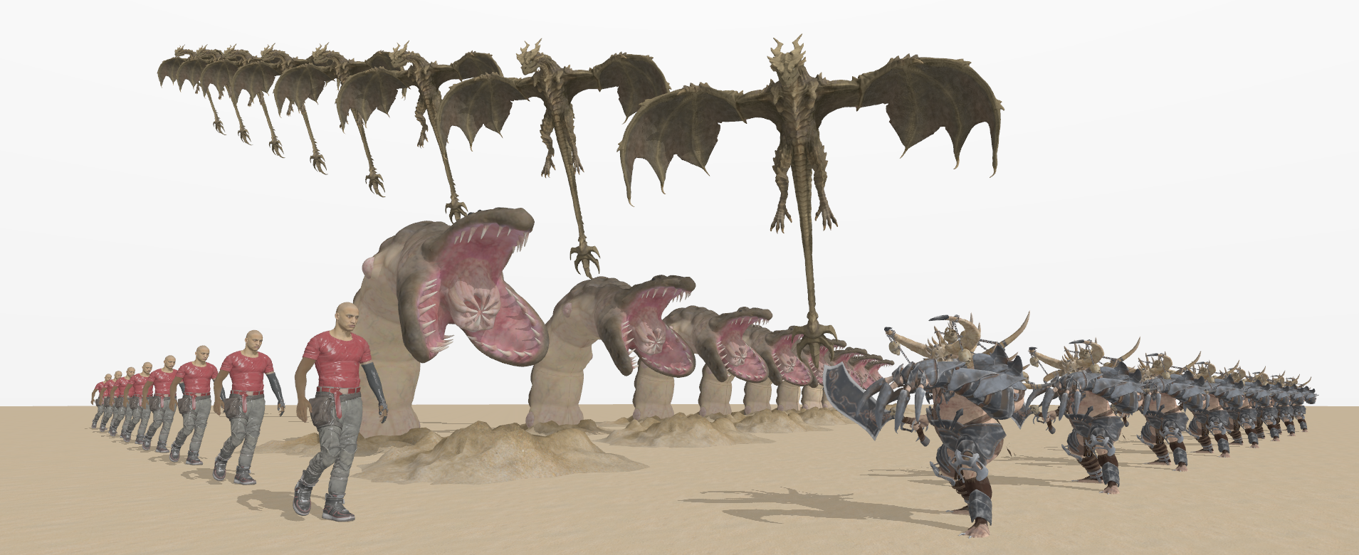
Figure 3: A screenshot of our evaluation scene that shows multiple different animated 3D models. Notably, instances of the same model type are not rendered with instanced rendering, but all are individually animated and rendered—they just use the same animation clips and times.
It must be noted, however, that the results reported in this section do not come automatically by just using task and mesh shaders. A substantial amount of optimizations had to be implemented to get there in both cases—essentially following the guidelines presented by Arseny Kapoulkine in his YouTube video series. As stated in the introduction, graphics programmers are now responsible for good rendering performance, unlike classical graphics pipelines, which provide generally good performance out of the box for many use cases.
The exact reasons for the better performance of mesh shading cannot be stated definitively for all scenarios, but most available sources point to issues with the fixed-function input assembly stage, which can stall if its dedicated memory fills up too quickly. This can be a result of cache-inefficient index buffer layouts, or “fat vertices”, as analyzed in The performance impact of vertex shader exports by Kostas Anagnostou. Meshlets, on the other hand, are small clusters of vertices with typically high positional locality and vertex sharing as well. Citing Coming to DirectX 12— Mesh Shaders and Amplification Shaders: Reinventing the Geometry Pipeline by Sarah Jobalia:
A meshlet is a subset of a mesh created through an intentional partition of the geometry. Meshlets should be somewhere in the range of 32 to around 200 vertices, depending on the number of attributes, and will have as many shared vertices as possible to allow for vertex re-use during rendering. This partitioning will be pre-computed and stored with the geometry to avoid computation at runtime, unlike the current Input Assembler which must attempt to dynamically identify vertex reuse every time a mesh is drawn.
These aspects ultimately allows geometry processing in a more parallel way, as stated in the DirectX specification:
From the hardware perspective the goal is to remove the need for the index processing part of the IA and allow GPUs to be more parallel.
But What About Tessellation?
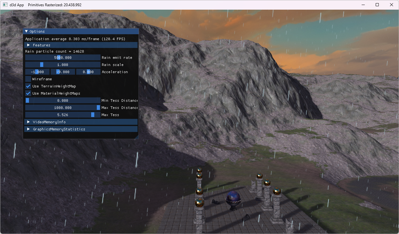
Finding examples for comparing hardware tessellation with mesh shading-based tessellation proved a bit challenging. I was finally able to find one in the book Introduction to 3D Game Programming with Direct3D 12.0, 2nd edition and its accompanying source code. The sample applications Terrain and TerrainMS both implement terrain subdivision, using either the fixed-function tessellator (with hull and domain shaders) or amplification and mesh shaders, respectively. Table 2 summarizes the rendered output alongside measured frame rates.
| Terrain | TerrainMS |
|---|---|
 |
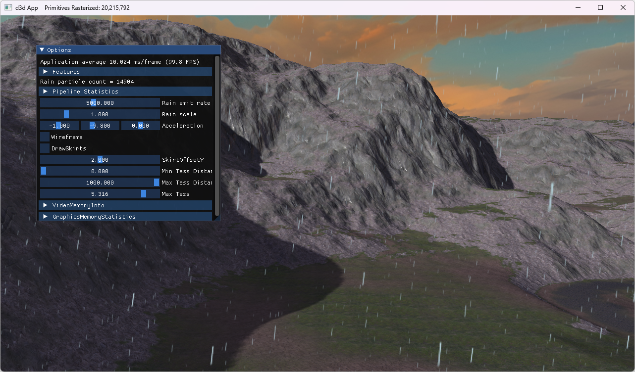 |
| Hardware tessellation | Mesh shading-based tessellation |
| 20.4M triangles | 20.2M triangles |
| 144 FPS | 119 FPS |
Table 2: Performance comparisons of a hardware tessellation-based implementation and its mesh shading-based counterpart. Both approaches subdivide the input terrain to rasterize over 20 million triangles, measured on an RTX 4060 Ti.
The performance results in Table 2 indicate a 21% performance advantage for traditional hardware tessellation. The difference is even bigger in favor of hardware tessellation in one of our own research projects: I’ve created a mesh shading-based alternative tessellation implementation to replace the hardware tessellation-based implementation of our paper Fast Rendering of Parametric Objects on Modern GPUs. Porting the tessellation implementation to task and mesh shaders resulted in reducing the FPS to about a quarter (-76% performance). I am confident that performance can be optimized, but it is a rather dire starting point. Once again, using classical graphics pipelines with tessellation enabled delivers good performance out of the box—mesh shading demands figuring out performance optimizations from graphics programmers before it becomes a competitive alternative.
With the original hardware tessellation approach from our paper, parametric patches (quads) are submitted individually to graphics pipelines and subdivided with factors of up to 64×64. A direct mapping of this strategy to task and mesh shaders would imply a workgroup size of 1 due to a peculiarity regarding payloads (more details further down below):
layout(local_size_x = 1, local_size_y = 1, local_size_z = 1) in;
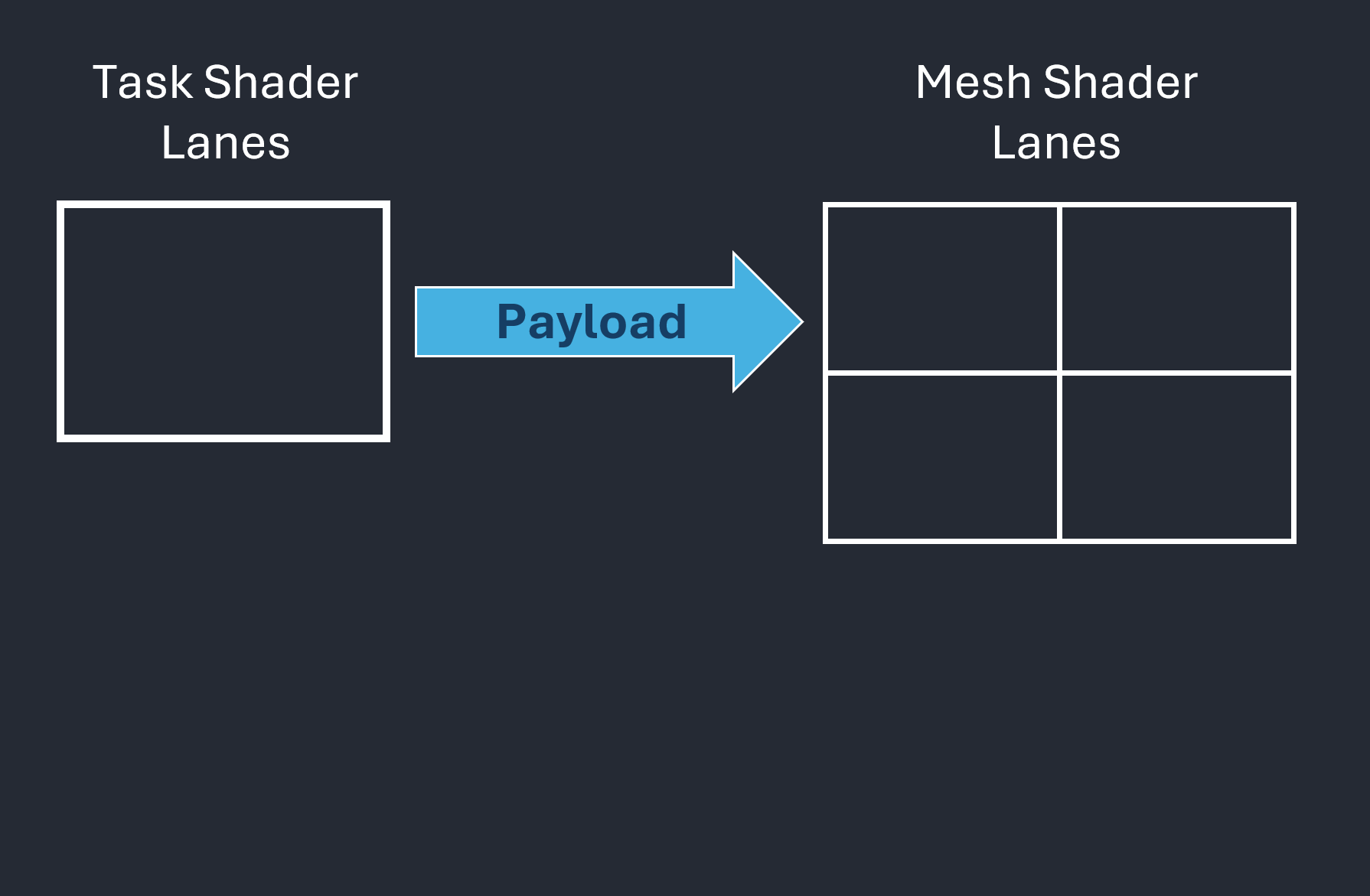
This approach, however, leads to underutilized lanes within the workgroup. To fully leverage GPU parallelism, workgroup sizes should be at least 32 threads on NVIDIA architectures and 64 on AMD. Increasing the workgroup size reveals another difficulty: only one single payload can be transferred between task and mesh shaders, as illustrated in Figure 4.
 |
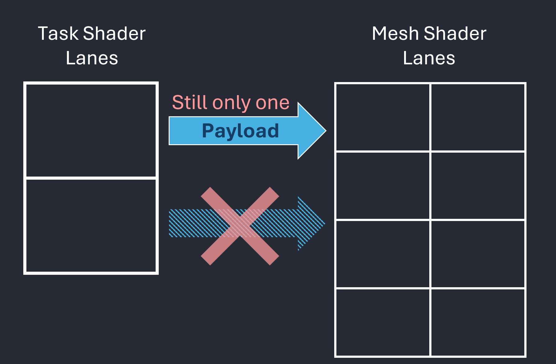 |
| Figure 4.1: Data transfer from task shader to mesh shader through a payload | Figure 4.2: Regardless of how many lanes, there is always only one payload per workgroup. |
Figure 4: These figures focus on the payload, which is data (typically small) passed from a task shader workgroup to its associated mesh shader instances.
So, we actually want something like
layout(local_size_x = 32, local_size_y = 1, local_size_z = 1) in;
but this quickly leads to challenges with respect to arranging the size-limited payload in a useful manner since we cannot have different payloads for different lanes. Between tessellation control and tessellation evaluation shaders, we can have exactly that. The following is the “payload” transferred between them in our implementation via patch attributes and varying attributes—and the GPU efficiently handles this setup, leading to high FPS:
layout (location = 0) out PerControlPointPayload
{
    vec2 mParams;
} control_out[];

layout (location = 1) patch out PerPatchPayload
{
    uint mObjectId;
    uvec3 mUserData;
} patch_out;
While an optimized solution may exist and would probably reduce or eliminate the observed performance gap, such an implementation is not immediately apparent. The key takeaway is that mesh shading does not provide a drop-in, high-performance replacement for all use cases. Although the tessellation pipeline has its own limitations, and its API has arguably also been a bit bent to our use case, it proved well-suited to our scenario and delivered consistently high performance.
Conclusion
In its current form, amplification/task and mesh shaders do not appear to me as being a universal replacement for hardware tessellation. The primary limitations stem from payload handling and task shader constraints:
- A task shader workgroup can have only one payload.
- Only the first lane of a workgroup is allowed to declare how many mesh shader instances to spawn for the entire workgroup. (See SPIR-V registry regarding
EmitMeshTasksEXT, and the DirectX specification regardingDispatchMeshintrinsic). - Smaller workgroup sizes typically underutilize GPU parallelism.
- Payload size is expected to remain small (e.g., less than 236 or 108 bytes, as suggested in Using Mesh Shaders for Professional Graphics by Christoph Kubisch).
While I believe that highly optimized graphics mesh pipelines may achieve performance parity with hardware tessellation in certain scenarios, the tessellation pipeline remains significantly simpler to program because it does not require programmers to implement all kinds of optimizations for good performance. This simplicity yet good performance reflects years of vendor-driven optimization in workload distribution across GPU architectures, as described as Work Distribution Crossbar in Fast Tessellated Rendering on Fermi by Tim Purcell.
The only real benefit of amplification/task and mesh shaders in tessellation scenarios appears to be their support for controlled and well-defined subgroup operations, like in conventional compute shaders. I welcome further discussion down below, and I’m particularly interested in counterarguments or descriptions of mesh shading features that I have overlooked in my analysis. In any case, I am curious how mesh shaders will evolve with future extensions and improvements.
Comments