Setting Up a Proper Projection Matrix for Vulkan
In this post, I’d like to describe a strategy how a proper and (hopefully) easy to understand perspective projection matrix for Vulkan can be set-up manually. Figure 1 gives an overview of some commonly used spaces. Some spaces must follow certain rules that are dictated by the graphics API—i.e. Vulkan for the scope of this blog post.

Figure 1: The spaces displayed with yellow borders and fonts (world space and view space) can be chosen freely by programmers. But for the other spaces, Vulkan dictates certain requirements s.t. its fixed-function steps polygon clipping, homogeneous division, and backface culling (in that order from left to right, marked with circular symbols) lead to the expected result. All of the spaces are required to be in a right-handed coordinate system. I.e., Vulkan’s fixed-function steps operate so that they expect the input geometry to be defined with right-handed coordinates.
A more detailed picture of the spaces with special requirements is given in Figure 2. It can be observed that the basic structure of them all is very similar and consistent: Each space is defined with a right-handed coordinate system where the x axis points to the right, and the y axis points down. Now, “right” and “down” might be terrible descriptions of the matter, but at least if we follow these thoughts through to the framebuffer space and imagine a framebuffer being rendered on a screen, they should hopefully get the point across. I.e. an image (in framebuffer space) is drawn to the screen s.t. its origin is assumed to be in the top-left corner, ascending x coordinates refer to pixels from left to right on the screen, and ascending y coordinates refer to pixels from top to bottom on the screen. The z axis pointing “into” the screen shall indicate that depth values increase the further away an object is.
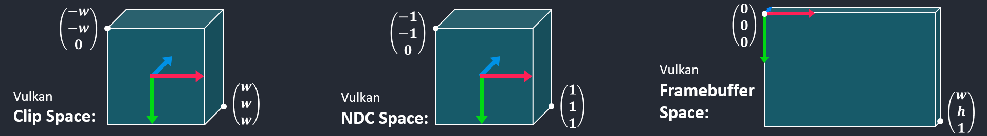
Figure 2: The spaces which Vulkan works with and performs fixed-function operations in are all assumed to be given in a right-handed coordinate system with matching axes orientations. While clip space coordinates are given in homogeneous space, normalized device coordinates only contain primitives within the unit cube from $(-1, -1, 0)^T$ to $(1, 1, 1)^T$. Framebuffer space’s x and y coordinates range from $ [0..w) $ and $[0..h)$, with $w$ referring to the framebuffer’s horizontal resolution, and $h$ referring to the framebuffer’s vertical resolution. The z coordinates refer to depth values in $[0,1]$ range.
Into View Space
Let us start with the transformation of our coordinates into view space. Since we are totally free to define view space according to our specific requirements or preferences, let us assume that we have already set up a matrix $\mathbf{V}$ which transforms coordinates from world space into view space. This can be done by plugging the camera’s (transformed) coordinate axes ($\mathbf{c_x}$, $\mathbf{c_y}$, and $\mathbf{c_z}$) together with its translation vector $\mathbf{c_t}$ into the columns of a matrix and computing the inverse of it, which gives view matrix $\mathbf{V}$:
\[\mathbf{V} = \begin{pmatrix} \mathbf{c_{x_x}} & \mathbf{c_{y_x}} & \mathbf{c_{z_x}} & \mathbf{c_{t_x}} \\ \mathbf{c_{x_y}} & \mathbf{c_{y_y}} & \mathbf{c_{z_y}} & \mathbf{c_{t_y}} \\ \mathbf{c_{x_z}} & \mathbf{c_{y_z}} & \mathbf{c_{z_z}} & \mathbf{c_{t_z}} \\ 0 & 0 & 0 & 1 \end{pmatrix}^{-1}\]Equation 1: Construction of a view matrix from three cooordinate axes $\mathbf{c_x}$, $\mathbf{c_y}$, $\mathbf{c_z}$, and a translation vector $\mathbf{c_t}$, each in world space, referring to the camera’s orientation and position.
Prepare for Perspective Projection
For the sake of comprehensibility, I would like to propose an intermediate step between the view matrix and the (in our example: perspective) projection matrix. With this intermediate step, the projection matrix will be easier to explain and straight-forward to build.
I am proposing to transform our coordinates into the “Vulkan form” here, meaning that we transform everything into the shape of the coordinate systems from Figure 2. As an example, let us assume a right-handed view space coordinate system where the y axis points up in world space (at least if pitch and roll angles are zero), and the camera’s view direction is aligned with the camera’s local -z direction. Again, you are completely free to define view space in a different way, but this is the way chosen for this example. Figure 3 shows the transformation which prepares for Vulkan’s clip space and further spaces.

Figure 3: We want to transform coordinates so that the resulting z axis points into the camera’s view direction, s.t. that part of the scene will be contained in the clip space cube. Furthermore, we must maintain a right-handed coordinate system, where x and y axes correspond to ascending horizontal coordinates towards the right, and ascending vertical coordinates downwards, w.r.t. framebuffer space.
From $\textbf{V}$ space, we can easily set up the required transformation by just looking at the resulting axes in Figure 3. The x axis remains unchanged, y and z axes must be flipped to get the desired coordinate system. Plugging these transformations into a matrix and taking the inverse of it transforms into the desired intermediate space which we call $\textbf{X}$:
\[\mathbf{X} = \begin{pmatrix} 1 & 0 & 0 & 0 \\ 0 & -1 & 0 & 0 \\ 0 & 0 & -1 & 0 \\ 0 & 0 & 0 & 1 \end{pmatrix}^{-1}\]Equation 2: An intermediate transformation which aligns the axes with the expected format of Vulkan’s fixed-function steps.
Perspective Projection Into Clip Space
The final step is transforming from $\textbf{X}$ into clip space with perspective projection. Since all axes have already been aligned properly in the previous step, we can focus on the projection itself in this step and do not have to spend any thoughts on any more axis flips that might be required (as opposed to the OpenGL way that was discussed in a previous blog post).
\[\mathbf{P} = \begin{pmatrix} \frac{a^{-1}}{\tan \frac{\phi}{2}} & 0 & 0 & 0 \\ 0 & \frac{1}{\tan \frac{\phi}{2}} & 0 & 0 \\ 0 & 0 & \frac{f}{f - n} & -\frac{nf}{f-n} \\ 0 & 0 & 1 & 0 \end{pmatrix}\]Equation 3: Perspective projection matrix, where $a^{-1}$ is the framebuffer’s aspect ratio $\frac{h}{w}$, $\phi$ is the field of view, $n$ is the distance of the near plane, $f$ is the distance of the far plane.
The x and y coordinates are transformed based on the perspective distortion calculated from the field of view and the aspect ratio. z coordinates are scaled based on near and far plane parameters and offset through the $-\frac{nf}{f-n}$ matrix entry. The z value ends up in the homogeneous coordinate, leading to the perspective divison at the homogeneous division fixed-function step.
If it is not obvious from Equation 3 yet that no axes are inverted by $\mathbf{P}$, it can be examined exemplarily by assinging easy-to-follow values (let them be $a=1$, $\phi = 90^{\circ}$, $n=1$, $f=2$) and computing the result of transforming a generic vector $(x, y, z, 1)$ with $\mathbf{P}$ using WolframAlpha and observing that $z$ is transformed to $2z-2$, which means that it is not flipped, only shifted a bit towards the camera’s position—corresponding to the near plane.
Putting Everything Together
Combining Equations 1 to 3 gives matrix $\mathbf{C}$ which transforms coordinates from world space into a clip space which is suitable to be used with Vulkan:
\[\mathbf{C} = \mathbf{P} \mathbf{X} \mathbf{V}\]Equation 4: Combining the matrices by first transforming world space into view space with $\mathbf{V}$, then preparing them for the perspective transformation by transforming them with $\mathbf{X}$, and finally applying perspective projection via $\mathbf{P}$ gives matrix $\mathbf{C}$ which transforms from world space into clip space. Comparing this approach to Figure 1, we actually have one additional space as can be seen in Figure 4.

Figure 4: We have introduced an additional space transformation between view space and clip space, which is totally fine since we basically can do what we want as long as we provide Vulkan with proper clip space coordinates, s.t. its fixed-function steps compute the right results for us.
As a closing remark I would like to point out that the transformation into $\mathbf{X}$ as an intermediate step might not be necessary depending on your particular application’s setup. You might, for example, just define view space to be $\mathbf{X}$-space already, or you might “bake” the transformations from $\mathbf{X}$ into your projection matrix. However, splitting the transformations as presented in this blog post shall serve a didactic purpose—namely to explain the differnt transformations and how they can be created manually without requiring any functions of 3rd party libraries.
Comments