Why projection matrices typically used with OpenGL fail with Vulkan
When programmers with an OpenGL background learn Vulkan, they often expect—or hope—that the projection matrices they have used with OpenGL continue to work with Vulkan. Everyone with such expectations is in for a bad surprise. While many sources on the internet offer strategies to fix it such as
- Inverting the projection matrix’ y-axis:
projMat[1][1] *= -1, - Inverting the y coordinates in the vertex shader:
gl_Position.y = -gl_Position.y;, - Flipping the viewport by specifying a negative height,
- Changing the front faces from
VK_FRONT_FACE_COUNTER_CLOCKWISEtoVK_FRONT_FACE_CLOCKWISE.
Applying such changes without really knowing what’s going on under the hood can leave a bad feeling in the mind of a thoughtful programmer. This blog post tries to explain why OpenGL’s projection matrices do not work in a Vulkan application without modification and what the fundamental differences between the two APIs are in this specific case.
Projection Matrices in OpenGL
Before we can analyze the differences between Vulkan and OpenGL, we might be interested in getting a feeling for typical OpenGL projection matrices which look like follows:
\[\begin{pmatrix} \frac{2 n}{r - l} & 0 & \frac{r + l}{r - l} & 0 \\ 0 & \frac{2 n}{t - b} & \frac{t + b}{t - b} & 0 \\ 0 & 0 & -\frac{f + n}{f - n} & -\frac{2 f n}{f - n} \\ 0 & 0 & -1 & 0 \end{pmatrix}\]Equation 1: Typical OpenGL projection matrix as generated by good old glFrustum (or with better formatting here: Scratchpixel 2.0 - The Perspective and Orthographic Projection Matrix).
Such a projection matrix might look a bit complicated at first glance, but the fundamental ideas are not so involved once we simplify it a bit. The variables refer to: near plane distance $n$, far plane distance $f$, left and right frustum boundaries $l$ and $r$, top and bottom frustum boundaries $t$ and $b$. These parameters are for transforming a scene into a unit cube. Let us simplify computations by assuming that our entire scene is contained within unit cube bounds already, then the projection matrix looks a lot simpler turns from its form in Equation 1 into the form in Equation 2:
\[\begin{pmatrix} 1 & 0 & 0 & 0 \\ 0 & 1 & 0 & 0 \\ 0 & 0 & -3 & -4 \\ 0 & 0 & -1 & 0 \end{pmatrix}\]Equation 2: Projection matrix with parameters $l = -1$, $r = 1$, $b = -1$, $t = 1$, $n = 1$, and $f = 2$.
What a projection matrix like the one shown in Equations 1 and 2 does can be visualized with the animation in Figure 1. The key points of this transformation are the following:
- It transforms a frustum that is oriented into the direction of the negative z axis into a unit cube
- It flips the z axis, which corresponds to changing the handedness of the coordinate system
Figure 1: Visualizing the key points of an OpenGL-style projection matrix: The part of the scene that is positioned along the negative z axis gets perspectively transformed, and the underlying coordinate system changes.
Applying such a perspective transformation would, of course, not gradually convert the coordinate system as shown in the animation, but instantly through matrix transformation of a vector. The animations in Figure 1 shall serve the purpose of demonstrating what’s happening.
We can exemplarily calculate one specific vector which was positioned in front of the camera (which is by convention towards the negative z axis, as stated above) by transforming a homogeneous 3D vector on the far plane with Equation 2. We get the following result:
\[\begin{pmatrix} 1 & 0 & 0 & 0 \\ 0 & 1 & 0 & 0 \\ 0 & 0 & -3 & -4 \\ 0 & 0 & -1 & 0 \end{pmatrix} \cdot \begin{pmatrix} 1 \\ 1 \\ -2 \\ 1 \end{pmatrix} = \begin{pmatrix} 1 \\ 1 \\ 2 \\ 2 \end{pmatrix}\]Equation 3: Transforming a homogeneous 3D vector positioned on the far plane with the projection matrix from Equation 2. The resulting vector after homogenization is $(\frac{1}{2}, \frac{1}{2}, 1, 1)^T$.
While these projection matrices retain the signs of $x$ and $y$ coordinates, $z$ cooordinates get flipped. In our case, this means that our right-handed view space coordinates end up in a left-handed clip space coordinate system. The relevant spaces and fixed-function steps of a graphics pipeline are outlined in Figure 2. The projection matrix transforms coordinates into clip space, which is the space where the fixed-function steps primitive clipping and homogeneous division are performed, leading into normalized device coordinates (NDC space). Through viewport scaling, coordinates are transformed into framebuffer space (often called “window coordinates” in OpenGL). Afterwars the fixed-function step backface culling is performed.

Figure 2: Typical spaces in a 3D application include world and view space, which are generally user-defined. Graphics APIs dictate some conventions about other spaces, though, namely clip space, NDC space, and framebuffer space. Fixed-function steps (primitive clipping, homogeneous division, backface culling, from left to right) are indicated with circular symbols, while different spaces are indicated with rectangles.
Different Space Conventions in OpenGL and Vulkan
Different graphics APIs can have different conventions. This is also the case between OpenGL and Vulkan. Let us take a closer look the spaces of both APIs by observing Figures 3 and 4. They show the differences between OpenGL and Vulkan w.r.t. clip, NDC, and framebuffer spaces. We can actually observe for each of them that they differ in handedness. While in OpenGL every one of these spaces appears left-handed, Vulkan expects them to be right-handed. For framebuffer space, this blog post assumes increasing depth coordinates (i.e. the further away, the higher the depth value) to be aligned with the z axes wich are drawn in blue, and point in the direction of increasing positive values.
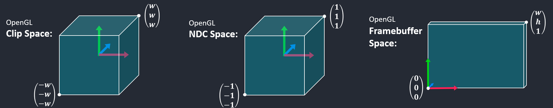
Figure 3: We can imagine all of OpenGL’s spaces to be given in left-handed coordinate systems—from clip space, to NDC space, and framebuffer space—under the assumption that that increasing depth values increase with the direction that “points towards the inside” of the screen.
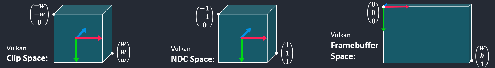
Figure 4: In constrast to OpenGL, we can imagine all spaces in Vulkan in a right-handed coordinate system throughout a graphics pipeline. The right-handed coordinate system naturally translates to Vulkan’s framebuffer space, which defines the coordinate origin in the top-left corner, with its x axis pointing to the right and its y axis pointing down.
From Figures 3 and 4 we can see clear differences between the two graphics APIs and this is the very reason why we get undesirable effects when using an OpenGL-style projectin matrix in Vulkan—rendered examples can be observed in Sascha Willems - Flipping the Vulkan viewport. The second key item besides different expected space orientations is the OpenGL specification’s formula for computing whether or not a polygon is backfacing or frontfacing (Section 14.6.1 Basic Polygon Rasterization, Equation 14.8) to the Vulkan specification, which also suggests a specific formula for this purpose (Section 27.12.1. Basic Polygon Rasterization). It almost looks the same as OpenGL’s formula, it just has an additional minus sign which makes all the difference. I.e., the formulae which determine if a polygon is frontfacing or backfacing that are used in both APIs internally indeed compute exactly the opposite results w.r.t. each other. While this formula does not exactly compute the cross product, we can use the cross product for making the same point: If it is used to compute a triangle’s face normal, the cross product is defined so that if vertices are given in counter-clockwise direction, its resulting vector (which serves as the face normal) is created according to the right-hand rule. By OpenGL flipping the results of the computation, this would correspond to an axis pointing in exactly the opposite direction.
How To Build a Projection Matrix for Vulkan?
Most of the strategies mentioned initially flip one axis of a given OpenGL-style projection matrix, turning the result into a right-handed clip space coordinate system. In particular, this applies to the first three items from above:
- Inverting the projection matrix’ y-axis:
projMat[1][1] *= -1, - Inverting the y coordinates in the vertex shader:
gl_Position.y = -gl_Position.y;, - Flipping the viewport by specifying a negative height (Further details can be found in Sascha Willems - Flipping the Vulkan viewport).
Changing the front faces from counter clockwise to clockwise can only be a partial solution. While it fixes which faces are being rendered, it fails to get the coordinate system right w.r.t. framebuffer space (compare between OpenGL and Vulkan in Figures 3 and 4), rendering the scene upside-down.
What I recommend is to avoid hacky solutions or such that fix OpenGL-style projection matrices entirely and instead, to build a nice, proper projection matrix for Vulkan as I have described in a different blog post: Setting Up a Proper Projection Matrix for Vulkan.
Comments